NSN 6110-01-195-3312
Part Details | DISTRIBUTION BOX
6110-01-195-3312 An enclosure which includes mounts, and protects such items as switches, circuit breakers, jacks, fuseholders, connectors, terminals and/or terminal boards, resistors, capacitors, transformers, and the like. It is primarily designed to distribute electrical power from one or more primary power source(s) such as generator(s) and battery(ies) to one or more electrical and/or electronic item(s). It may include a cover or door. For enclosures which include only circuit breakers, switches, jacks, fuseholders, terminals and/or terminal boards, see CIRCUIT BREAKER BOX; SWITCH BOX; JACK BOX; FUSE BOX and TERMINAL BOX. For enclosure primarily designed to interconnect two or more electrical and/or electronic items, except primary power source(s) see INTERCONNECTING BOX. For empty boxes which are designed to mount, but do not include electrical devices such as switches, jacks, fuseholders, terminals and/or terminal boards, see JUNCTION BOX. See also INTERCONNECTING CABINET; CONTROL (as modified); PANEL (1) (as modified); RELAY ASSEMBLY; PANEL, POWER DISTRIBUTION; SWITCHBOARD (as modified) and PANEL, FUSE. Excludes CONNECTOR-SWITCH.
Alternate Parts: 6976ED117, 6110-01-195-3312, 01-195-3312, 6110011953312, 011953312
| Supply Group (FSG) | NSN Assigned | NIIN | Item Name Code (INC) |
|---|---|---|---|
| 61 | NOV 28, 1984 | 01-195-3312 | 19735 ( DISTRIBUTION BOX ) |
REFERENCE DRAWINGS & PICTURES
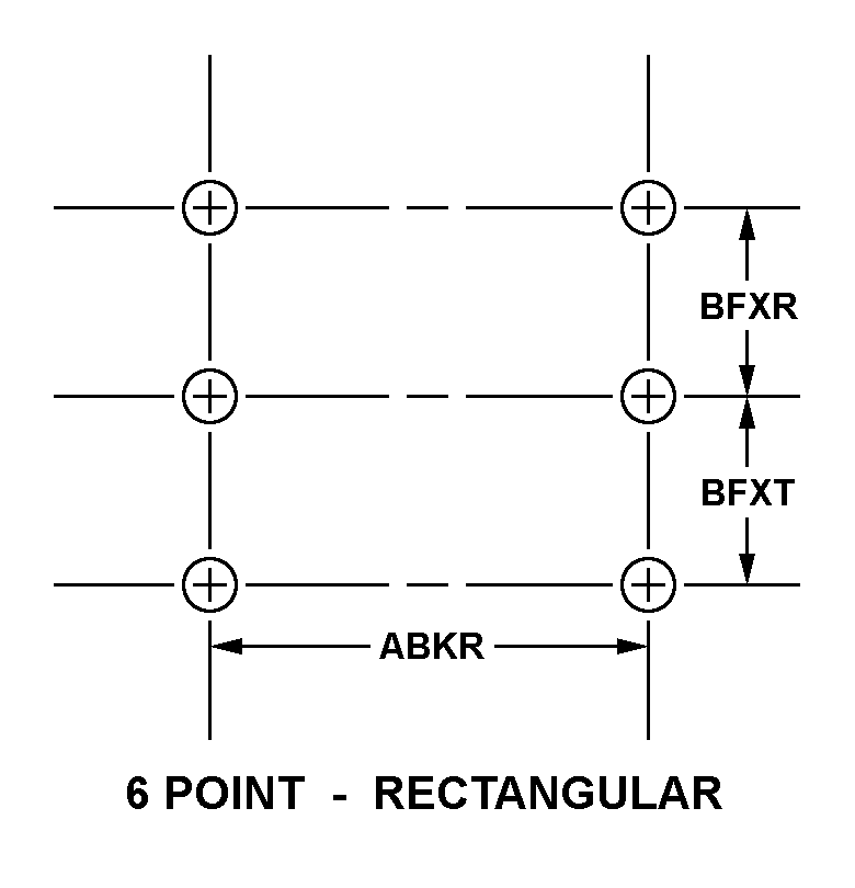
6 POINT-RECTANGULAR
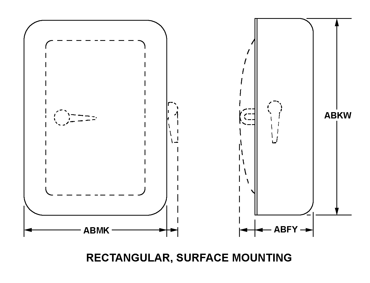
RECTANGULAR, SURFACE MOUNTING
Cross Reference | NSN 6110-01-195-3312
| Part Number | Cage Code | Manufacturer |
|---|---|---|
| 6976ED117 | 27192 | DRS POWER & CONTROL TECHNOLOGIES,INC |
Technical Data | NSN 6110-01-195-3312
| Characteristic | Specifications |
|---|---|
| STYLE DESIGNATOR | RECTANGULAR, SURFACE MOUNTING |
| OVERALL DEPTH | 18.000 INCHES NOMINAL |
| OVERALL HEIGHT | 79.000 INCHES NOMINAL |
| OVERALL WIDTH | 30.000 INCHES NOMINAL |
| MATERIAL | STEEL |
| MOUNTING METHOD | UNTHREADED HOLE |
| STANDARD MOUNTING PATTERN DESIGNATOR | 6 POINT-RECTANGULAR |
| CENTER TO CENTER DISTANCE BETWEEN MOUNTING FACILITIES PARALLEL TO WIDTH | 12.500 INCHES NOMINAL |
| FIRST CENTER TO CENTER DISTANCE BETWEEN MOUNTING FACILITIES PARALLEL TO THE HEIGHT | 12.500 INCHES NOMINAL |
| SECOND CENTER TO CENTER DISTANCE BETWEEN MOUNTING FACILITIES PARALLEL TO THE HEIGHT | 12.500 INCHES NOMINAL |
| UNTHREADED MOUNTING HOLE DIAMETER | 0.781 INCHES NOMINAL |
| SYSTEM FOR WHICH DESIGNED | THREE WIRE THREE PHASE |
| MAIN LINE MAXIMUM AC VOLTAGE RATING IN VOLTS | 440.0 |
| FUSE TYPE AND QUANTITY ACCOMMODATED | 4 INDICATOR CARTRIDGE AND 3 INDICATOR CARTRIDGE |
| FUSE CURRENT RATING IN AMPS | B6.0$$B10.0 |
| HAZARDOUS LOCATIONS/ENVIRONMENTAL PROTECTION | SPRAYTIGHT |
| FEATURES PROVIDED | INDICATOR LAMPS |